Guralp CMG-40T Intermediate Sensor

Salient Features:
- Flat response to velocity from 30 seconds to 50 Hz
- Low power
- Easy to use - No Mass lock/unlock; Masses are free to move at all times
Installation Tips:
Manufacturer Documents:
Response Characteristics:
PASSCAL Field Note
Guralp CMG-40T Installation and Operation:
Installation and operation of PASSCAL CMG-40T seismometers is briefly summarized here; full details of the sensor and sensor operation are provided in the manufacturer's operations, Manual (HTML)
Sensitivity = 2 x 400 V/m/s nominal (differential)
Zeros: two at zero
Poles: two at -0.1481 +/- 0.1481i (30 second two-pole corner)
Sensor consumes 80mA @ 12 VDC (10-36 VDC)
Fuse: one 1-Amp 5x20 mm
Autocentering: Not available as an option with the PASSCAL 40T
Mass locking: Not needed with the CMG-40T
Contents and Tools Required:
- The reusable shipping container will include one CMG-40T sensor and one cable, which connects the sensor to the recorder.
- Care should be taken at all times in handling the shipping case to ensure that the case remains a safe and durable container for shipping of the sensor.
- A Guralp hand-held control unit (HCU) is useful but not necessary for deployment of the CMG-40T sensor. Other installation tools may include shovels, materials for a vault or enclosure of some sort, and a level and compass to prepare the pad for placement of the sensor.
Packing and Shipping:
Place the sensor in the foam cavity; be sure to replace the circular foam "cap" over the top of the sensor (this is critical to restrain the sensor from moving up and down within the case). The cable should fit snugly around the foam "cap". Be careful not to close the case lid down on the cable!
Keep each sensor matched to the same case and cable assembly. Referring to the shipping manifest can answer any question as to what sensor was shipped in what case- and can make returning the equipment much more simple.
For domestic shipping, PASSCAL strongly recommends the use of FedEx; their service is consistently better and their tracking service is quite useful. No additional insurance is required when shipping PASSCAL equipment.
Installation:
- A hard, level surface should be prepared and marked with a 12-inch line along the desired azimuth (most often true north/south). Marking the pad and using that azimuth for subsequent installations (if necessary) guarantees consistency.
- Before placing the sensor on the pad, check that the three leveling feet and lock nuts are free to turn, and that the cabling will reach the necessary destination with some slack to spare.
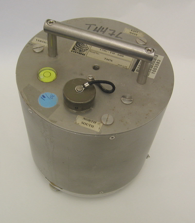
- Place the sensor on the pad and align to the desired azimuth. Pointers near the base of the sensor make this easier- the brass points north, the steel to the south.
- Level the sensor by turning the feet until the bubble of the level mounted in the top plate of the sensor is in the center. Re-check the alignment of the sensor, as the sensor may walk slightly during leveling. Lock the feet in place by tightening the lock nuts against the case.
- Attach the sensor cable to the connector at the top of the sensor and place in the vault or enclosure such that tugs do not pull on the sensor. Usually the cable can be wedged in a corner or wire-tied to the pass-through pipe where it extends into the vault. Plug the the other end of the sensor cable into DAS analogue input Port, usually labeled Chan 1-3 or Sensor A. The sensor will be powered when it is connected to the recorder.
- No mass unlocking is necessary. However, handle the sensor with care, as careless handling can still damage the unit.
- Check the mass position voltages with the DAS (see install sheet). Mass positions should optimally be within +/- 2.0 Volts; if readings are higher, refer to the section entitled "Mass Position Adjustments".
- Monitoring the sensor output is helpful (link) but an overnight data recording session is best to determine if the sensor is operating correctly (a huddle test with multiple sensors at a central site is the optimal test).
- Complete installation by covering sensor vault with dirt (if using a temporary underground vault) or with enclosure (if installing sensor above ground).
- Note that at no time does the sensor case require opening.
Mass Position Adjustments (only done IF the mass pos Voltages are >2.0V):
The mass position outputs of the CMG-40T are adjusted at PASSCAL to a nominal value of +/- 100 mVolts, but will vary to a certain degree based upon factors such as inaccurate leveling or rough handling; PASSCAL does not recommend making this adjustment unless the mass positions are outside of the range of +/- 2.0 Volts.
If the mass positions must be adjusted, follow the following procedure:
- Make sure that the work is done in a clean, dust-free environment. You do not need a DAS, if you have the hardware and cables in step 3, below.
- Set the sensor on a hard, level surface and level the sensor as exactly as possible; lock the legs in place.
- Connect the sensor cable to a Guralp Handheld Control Unit HCU and a Guralp power cable from the HCU to 12V.
- Flip the HCU toggle switch near the middle of the unit to the "1 SEC VEL" setting such that the sensor has a 1 Hz response. This will allow the mass-position output to respond faster to offset changes
- Remove the sensor offset adjustment port screws mounted in the top plate of the sensor. These are marked nearby on the top plate with the labels "Vertical", "East/West", and "North/South". Only remove the screw for the component(s) that is out of range.
- Keep the screws in a handy, clean place so as not to lose them or their O-rings.
- Using a slotted screwdriver with a blade no wider than 0.5 mm and no longer than 4 mm, turn the offset potentiometers mounted on the top circuit board inside the sensor to adjust the offset. Some of the PASSCAL sensors have a small aluminum cone guide mounted around the potentiometer to ease the adjustment, while a small flashlight is useful for making the adjustment on those that are not equipped with the cone guide. Monitor the mass positions during adjustment. The mass positions can be measured by 2 methods with the HCU- one by reading the analog meter when the "MASS POS" switch is at the appropriate channel, and the other by using a voltmeter and referencing the appropriate banana jacks - "MASS POS" (blue, on the right) and "GND" (green, at the bottom).
- Replace the sensor offset adjustment port screws.
- Flip the toggle switch back to the "BB VEL" setting, and disconnect the HCU, Now reattach the 40T to the digitzer.