Guralp CMG-3T Broadband Sensor
Salient Features:
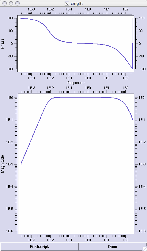
- 120s - 50 Hz flat velocity response
- Remote electronic mass locking, unlocking and centering.
Installation & Troubleshooting Documents:
Manufacturer's Documents:
Response Characteristics:
Other Documents:
Installation Tips:
- The sensor pad should be within 5° of level, marked with lines oriented north and east. Construction of the sensor enclosure is critical to data quality.
- Try to keep the sensor cool during the set up phase. Align the brass sensor-orienting pin to north; the silver sensor-orienting pin to south. Level the sensor by adjusting the feet to center the bubble level. Twist the top part of the foot mechanism down (clockwise) onto the bottom part to lock it.
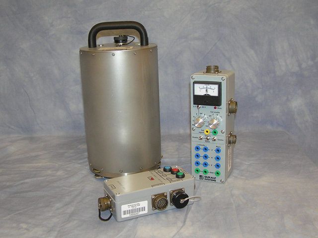
- Attach the sensor cable, seat it all the way in. Secure the sensor cable so that tugs on it (inadvertent or otherwise) do not budge the sensor and attach the other end to the grey break-out box if it is not attached already.
- Connect the break-out box to the digitizer with the CMG3T to digitizer (RT130 or Q330) cable. This will power the sensor, so proceed quickly to unlock the masses.
- Unlock the masses using the controls on the break-out box, cover the sensor with insulation, insulate the vault and close the vault.
- Center the sensor using the handheld controller attached to the digitizer or by using the buttons on the break-out box and measuring the mass position voltages with a multimeter. The voltage should be within 1.5 volts of zero. Wait 90 seconds between recentering attempts. If after more than 5 attempts an element mass position voltage still has not crossed zero, consult PIC staff for further instruction.
Cabling Notes:
There are two cable assemblies for the CMG3T:
- A 5 meter (a few 3 meter) grey cable with 26 socket mil-spec connectors at both ends, and;
- A black break-out box to DAS cable which mates with the break-out box on one end and the digitizer channel connector on the other end. The break-out box has ports to digitizer (recorder), sensor and optionally, the hand-held control unit. Power to the sensor is supplied from the digitizer connection through the cable to the break-out box, no separate power cable is required.
Photo Galleries:
Search Keywords:
PASSCAL, IRIS, Instrumentation, 3T, CMG-3T, Sensor, Seismometer
CRN: RER-17
- Home
- General Information
- Instrumentation
- Dataloggers
- Sensors
- All-In-One Systems
- Power Systems
- Field Procedures
- Controlled Sources
- Seismic Source Facility
- Magnetotelluric Systems at PASSCAL
- Ground Penetrating Radar
- Power and Memory Calculations Form
- Data Archiving
- Apply for a PI Account
- Experiment Scheduling
- Polar
- Important Hardware/Software Notes
- USArray
- Software


