Guralp CMG3-ESP Broadband Sensor

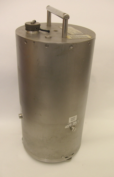
Salient Features
- 30sec to 50 Hz flat velocity response
- Manual Mass locking/unlocking
- Remote Mass Centering
Response Characteristics:
Installation & Troubleshooting Documents:
Other Documents:
Tips for installing CMG3-ESP seismometers.
Prepare the sensor vault. Install the power system. Check that the DC voltage levels and polarity is correct. Place the DAS in its enclosure and connect power.
Align and level the sensor. Place the sensor in the location it will remain for the duration fo the experiment. Align the brass point at the bottom of the sensor so it points NORTH. (The silver-colored point will point south.)
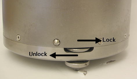
Level the sensor by adjusting the leveling feet. The top portion locks and unlocks the foot, and the bottom portion adjusts the height up and down. Lock the leveling feet when the bubble level is perfectly centered, i.e. when sensor is level.
Thread the symmetric sensor cable between the sensor vault the DAS enclosure to prepare for connecting it. Connect the symmetric sensor cable to the top of the sensor and the other end to the 'SENSOR' port at the top of the Breakout Box (BoB) in the DAS enclosure. Connect the second cable to the 'RECORDER' port of the BoB and now power the sensor by connecting the other end to the DAS analogue input port, e.g. Chan 1-3 or Sensor A, depending on the datalogger. It is the DAS that provides power to the sensor. The red Busy LED on the BoB should light up. This indicates that the power is connected and that one or more (hopefully all three) of the sensor components are locked. The sensor should not be connected to the DAS (and power) for too long before unlocking it.
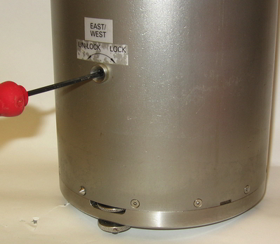
These seismometers have screw caps that must be removed in order to access the locking mechanisms. When the screw caps are removed, the inside of the sensor is exposed to the air, so you should avoid rainy or foggy weather or dust storms when you install an ESP. Be ready to catch the first screw cap released, because if the altitude is higher than the place where it was previously tightened, the positive pressure inside the sensor will push the cap.
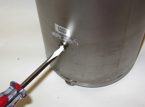
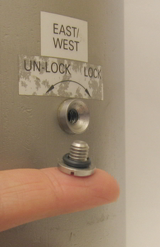
Remove each of the three cover plug screws from the side of the sensor case and use a 3mm Allen wrench to unlock each of the three components: vertical, north/south, and east/west. Use caution when inserting the 3mm Allen wrench into the hole. The wrench must be inserted a couple of centimeters and not always straight in. When it feels like the Allen wrench is in the hex nut (you can't see inside the sensor; you must feel your way), turn it counterclockwise approximately a quarter turn to unlock the component. You will have to overcome a little resistance, and that resistance varies from sensor to sensor and component to component. When all three components have been successfully unlocked the solid red Busy LED light on the ESP breakout box will go off. Now REPLACE the screw caps. First make sure an O-ring is on each one. Tighten the screws. If you forget this step and leave even one screw off, the sensor will be ruined in a couple months.
We repeat, REPLACE all three screw caps with O-rings and tighten them.
Center the sensor's masses. On the Breakout Box hold the Enable button and the Center button simultaneously to send a centering pulse to the sensor. The Red Busy LED should blink while the sensor is centering and turn off after the centering motors stop. All three components will probably be centered at this time, but you will check the 3 mass position voltages via the DAS. If any one is more than +/- 1.5Volts, you will repeat the centering command, either with the BoB buttons or with a command from the DAS.