Station Installation Procedure

Introduction:
PASSCAL station installations can vary according to the type of equipment being used, the physical environment, and also the legal responsibilities due the land owner or administrator. For the latter, it is assumed that the full consent of the land owner/administrator for the station to be installed, operated for the required duration, and then final removal has been obtained. It is further assumed that state laws regarding digging permits are also being followed. See also Guidelines for Station Installation.
Installing a PASSCAL seismic station involves the placement of a number of different, but coupled, sub-systems, including (but not limited to):
- Sensor(s)
- Power sub-system (batteries, solar power, utility company, etc)
- GPS timing system
- Data acquisition system (DAS)
- Communications equipment (if utilized)
- Cabling between these different sub-systems.
PASSCAL will provide the installation teams with “Installation Sheets”. These Installation Sheets represent a series of tasks that must be completed in the order presented, together with fields that require information to be entered. The Installation Sheets thus represent not only a complete record of the equipment that went into a particular station, but also a final check of its performance and sanity check for ensuring that the station is operating normally before departing the site. For more information on record keeping during installation, see the article here.
A simple station with easy vehicular access and soft ground to dig, consisting of sensor, DAS, GPS and battery power should take around 6 man-hours to install.
Sensor Vault (see also articles on seismic vaults and vault considerations):
In order to protect the sensor from the environment, weather and curious animals, and in order to minimize thermal variation, the sensor is often placed in a vault below ground level. The vault needs to be able to be sealed at the top to prevent water ingress. Simple vaults are often barrels obtained from hardware stores, and should be large enough to accommodate the sensor, and facilitate the orientation and leveling of the sensor.
The vault will need to be placed in a hole that is as least as large as the vault. Wise installers will dig a hole that is sufficiently large for the vault, and no larger. Larger holes require more effort to dig, are more damaging to the environment, and may provide less coupling between the sensor and the ground. The opening to the vault should be at least several inches above grade to prevent water ingress.
The bottom of the vault can be made of readi-mix/self-leveling concrete, with a ceramic tile impressed to provide a smooth surface on which to place the sensor. The concrete can be mixed on-site in a plastic tub or wheelbarrow tub. A minimum of 1/2 bag (25 lb) of concrete mix is sufficient, but more will be required depending upon the size of the hole that needs to be filled. The barrel can be pushed into the still-wet concrete to create a water-tight seal at the bottom of the vault.
Once the concrete has set, an orientation sign (North-South cardinal axis) should be drawn on the dry concrete or tile. This will help orient the sensor. Note that the compass used should be corrected for the difference between magnetic north and true north (i.e., magnetic declination). To determine magnetic declination for lat, long and a particular year, refer to: http://www.resurgentsoftware.com/geomag.html
The magnetic declination is set by turning the brass screw on the side of the Brunton compass box. For a west declination of say 16o (i.e., declination is 16o west of true north), turn the card west, i.e., counterclockwise (by turning the screw) so that the index pin points to 16o on the side of the card marked with 'W' in the quad scale, or 344o in azimuth scale. For an east declination of 16o, turn the card east (i.e., clockwise), so that the index pin points to 16o on the side of the card marked with 'E' in the quad scale, or 016o in azimuth scale.
Alternately, the sensor may be aligned to true north by first placing the sensor in the vault, and then holding the compass at least 3’ above the sensor. Do not place the compass near the sensor, as the mass and powerful magnets within the sensor will yield any compass reading erroneous.
The sensor should be kept cool during the journey to the site, and before it is placed in the newly constructed vault. Broadband sensors are highly sensitive to temperature changes, so all efforts to mitigate exposure to large temperature changes should be implemented.
When installing the sensor in the vault, ensure that the leveling feet are screwed as far into the body of the sensor as possible. Also, be very gentle when placing the sensor on the concrete pad to minimize sharp G-forces.
Any ports drilled in the vault that may allow water to enter should be thoroughly sealed with plumbers putty or silicone sealer. Note that silicone sealer will be more difficult to remove. Wise installers will also seal the lip between the vault and the concrete pad with plumbers putty in known wet environments.
Power subsystems:
If batteries are being used, they may be placed within the same vault as the DAS. If doing this, extreme caution must be excercised to prevent any object shorting between the battery terminals, which may damage equipment and cause injury to an installer. Wrap red electrical tape around the positive (+) battery terminal, and black electrical tape around the negative (-) battery terminal.
The use of solar panels makes the installation a little more complex and time consuming. Photovoltaic (PV) panels can be pole-mounted or ground-mounted. Ground mounts consist of an aluminum frame that must be assembled on site. The pole for a pole mount can be as simple as a 4”x4” wood board to which the mounting hardware, and then the PV panel, is affixed.
The PV panel should be placed sufficiently high above ground to avoid being covered by snow. The PV panel is aligned such that the panel faces the sun (south in the northern hemisphere and north in the southern hemisphere) and angled so as to maximize solar exposure when the sun is at its lowest elevation during the deployment. The panels (especially pole mounts) should also be placed as far as possible from the sensor vault to mitigate wind-coupled noise, but will be constrained by the cable length and the need for fencing the station to protect it from curious larger animals.
The pole mounts should be dug at least 18” into the ground, with at least 25 lbs of readi-mix concrete as a footing. Fence-post diggers work well here.
If Static Charge is a Problem (Remote/Autonomously Powered Stations)
An article describing proper practices for grounding of remotely-powered stations (not AC-powered), for stations where static charge is a problem, is available here.
GPS timing system:
The GPS antenna should be located at the top of a pole above the maximum anticipated snow depth, and with as clear view of the horizon as possible. Ensure that the top of the antenna is pointing “up”. The antenna may be mounted to the same frame as the PV panels, or may be placed on top of a 4”x4” post or T-post. Again, it should be placed as far from the sensor as cabling and site restrictions allow.
The cable connectors will attract water, so wrap the connectors with vulcanizing (self-sealing) rubber tape.
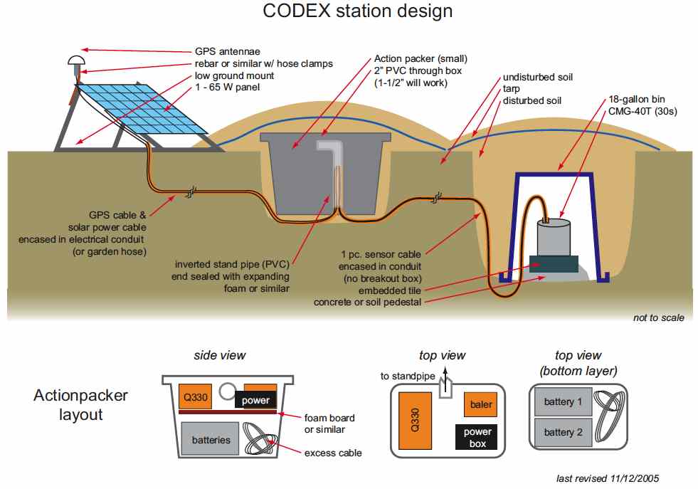
Station Housing:
The DAS is often co-located in an enclosure with the batteries. This ensures a neat site installation with minimal environmental impact, and keeps most of the cables together. The housing for the DAS, batteries, power distribution system, cables and any other station equipment should be sized correctly. If home fiberglass insulation is to be used in the case to keep the batteries cool and/or warm, sufficient room must be considered. The manufacturer Rubbermaid makes “Action-Packers” in several sizes that have been found to work well, although they are not completely weathertight. In areas where there is the possibility of the action-packer to fill with water, ensure that there are drainage holes in the bottom.
Communications sub-systems:
Stand-alone stations are the simplest to install. If communications for SOH or continuous real-time are being provided, sufficient space within the action-packer case must be provided for the communications equipment (and cabling, etc). Often the antenna will be mounted on the same pole as the GPS or the PV panels.
Cabling:
Cables between the various sub-systems lying on the surface are both a work hazard, and also are attractive to animals. Cables should be protected from tripping accidents and curious animals by shallow burial. In addition, cables need to be protected from damage, usually animals chewing on them. Cables can be protected by piping, such as PVC. Ensure that all cable connectors will stay dry for the duration of the deployment.
Applying power - Bringing the station to life:
Once the subsystems have been installed, it is time to connect the components and apply power. For a simple station, this process can be broken down into small tasks:
• Connect all cables EXCEPT power cables from the batteries;
• If the sensor needs to be unlocked, then:
• With the Streckeisen STS-2 and Guralp CMG3-ESP, use the appropriate screw or allen drivers to mechanically unlock the masses.
• With the Guralp CMG-3T, unlocking is accomplished via an electrical command issued from the “Break-out Box” (BoB). Wait until the blinking red LED is extinguished on the BoB and then check the mass positions which should now show increasingly small (< |1.5| volts) negative or positive voltages. An external 12V power source (connected to a BoB) may be used to perform the mass unlocking to conserve the primary batteries.
• Check that the battery voltage is correct and has the right polarity before connecting the batteries to a load (e.g. power box, DAS);
• Connect the power to the DAS, verify that the DAS boots by examining the status lights and/or display;
• Conduct the “Installation Sheet” tasks. See here for more details. Please have PASSCAL review the Installation Sheets you plan on using for your experiment, even if you downloaded them from the PASSCAL website. The Sheets may be tailored to your experiment, specifically the equipment you've borrowed. Plus datalogger firmware changes, newly discovered bugs, etc. necessitate revisions to these Sheets.
Departing the site:
Conduct final review of site for water drainage issues and dig drains to deflect running water away from the site if necessary. Cover the sensor vault and DAS enclosure with tarps. Carefully look around site for left tools, garbage, etc and remove from the site. Flagging may be placed on the pole mount to enable easy location of the site, though this can also draw unwanted attention. Additional flagging may be required by the landowner to indicate the location of the sensor vault. Clear and clean area, smoothing any holes that may have been dug and not filled. Leave the area as clean as possible so as not to invoke landowner annoyance.